
Congruity Aerospace, USA
Reciprocating-Airfoil (RA) Driven VTOL Aircraft
The reciprocating airfoils shaped like fixed wings and function as fixed wings during the cruise - A natural extension of fixed-wing aircraft with added capabilities for vertical takeoff and landing
For an aircraft to achieve vertical takeoff and landing (VTOL), the airfoil or wing disposed on the aircraft must move relative to the aircraft's main body to produce needed lift. The two most elementary motions are linear motion and rotation. Newton's First Law states that an object will remain at rest or in uniform motion in a straight line unless acted upon by an external force, which implies that the linear motion is the most preferred motion by nature. All vehicles, including cars, trains, watercraft, and aircraft, would travel largely along a straight path whenever permissible. However, the airfoil cannot undergo a linear motion in one direction indefinitely during VTOL operations because of the size limitation of the aircraft, and the only practical linear motion is reciprocating motion. The human being has tried helicopters based on rotary wings for more than 80 years with successes but also with challenges, and now it is time to try reciprocating-airfoil driven VTOL vehicles.
-- Dr. Yiding Cao, August 2019.
Video Narratives: During takeoff, most of the power is used to drive the RA wings. Once the aircraft is in the air, the propeller is turned on and the cruise speed of the aircraft increases. The power gradually shifts to the propeller, accompanied by a gradual reduction in the reciprocating speed of the RA wings because of the lift created by the airflow across the wings associated with the aircraft cruise speed. At a sufficiently high cruise speed (around 150 mph), the RA wings would completely stop reciprocating and function as fixed wings for lift.


Innovation
Why Reciprocating-Airfoil (RA) Driven VTOL Aircraft?
Fixed-wing Aircraft
-
Modern airfoils with an infinite span may attain a lift-to-drag ratio over 50 times under a rectilinear motion.
-
A fixed-wing aircraft with finite-span airfoils may have a lift 10 times higher than the thrust provided by an engine, resulting in a great leverage ratio by using the airfoils.
-
The fixed-wing aircraft have become mass transportation means in most countries.
-
However, the generation of a sufficiently high lift requires a substantially high aircraft speed, and consequently, a runway for aircraft takeoff or landing is needed.
Helicopter
-
Helicopters, primarily rotorcraft, have been developed for vertical takeoff/landing and easier maneuvering in the air at a low speed.
-
But the use of helicopters so far is rather limited, far from the goal of being a mass transportation means, due to vibratory loads in forward flight, very complex aerodynamic environments involving the wide and intense vorticity field released by the main rotor, and blade-vortex interactions. The intense vorticity field may cause adverse operational conditions for helicopters including tiltrotor helicopters, such as the vortex ring state.
-
Helicopters also have a poor safety track record based on their fatal accident rates in comparison with fixed-wing airplanes. Other issues include high costs, large footprint, and strong wind and loud noise during takeoff.
-
There are only about 26,500 civil helicopters in the world as compared to more than 1.0 billion motor vehicles.
A Grand Challenge
Elevating the use of vertical takeoff and landing (VTOL) aircraft to a mass transportation means may represent a grand challenge of the world, since VTOL aircraft may be a potentially more efficient and convenient means of transportation for passengers as compared to fixed-wing aircraft.
-
Revolutionize passenger transportation.
-
Improve the quality of people’s lifestyle.
-
Better utilize the territory of many countries.
-
For these purposes, reciprocating-airfoil driven aircraft are introduced.
Reciprocating-Airfoil (RA) driven Aircraft – A New Invention*
Airfoil forward stroke
Airfoil reverse stroke

A reciprocating airfoil may work in cycles, each including a forward and a reverse strokes. The airfoil moves back and forth within a limited stroke, and near each dead-end of the stroke rotates an effective angle while reversing the direction with a suitable, effective angle of attack. It may attain or exceed the performance of a fixed-wing with substantially linear motion, but without requiring a runway for the aircraft to achieve vertical takeoff and landing as well as hovering.
Note: The drawings are schematic for illustration purposes, and the airfoil shape shown may not represent an actual one to be used.
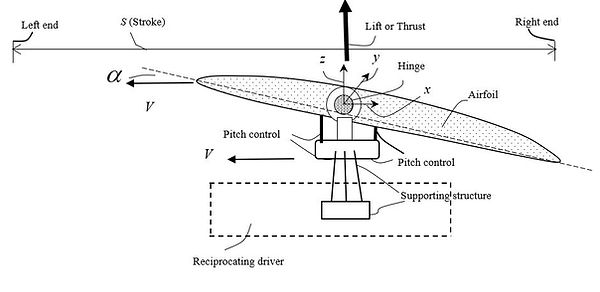
A Reciprocating Airfoil (RA) driven by a Crankshaft Mechanism

Schematic illustration of an Airfoil Assembly driven by a Crankshaft Mechanism
Animation of an Airfoil Module driven by a Crankshaft Mechanism
The airfoil can be driven by a suitable driver, such as a crankshaft, hydraulic, electric or electromagnetic
diver. The crankshaft has the advantage to convert rotation into reciprocating motion with energy loss only related to friction. With the use of roller interfaces, the friction between the track and the airfoil assembly is minimized. The RA stroke under the present setting may be on the order of meters. The distance between the airfoil and the track that is fixed to the vehicle or between the airfoil and the vehicle surface may be adjusted for different design considerations. Note that the crankshaft is deployed generally parallel to the vehicle surface herein, but it could be perpendicular to the surface to reduce the distance between the airfoil and the vehicle surface.
Reciprocating-Airfoil (RA) Modules to Balance Inertia Forces and Moments
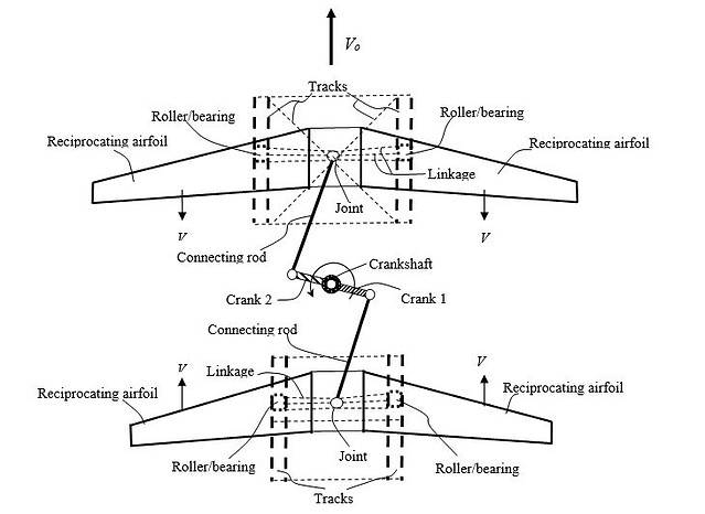
V: Reciprocating speed relative to vehicle/Vo: Vehicle flight speed
Schematic Illustration of a Top View of a Vehicle driven by an RA Module that Reciprocates in a Front-Back Direction of the Vehicle
For balancing purposes, reciprocating airfoils may be deployed in modules. An RA module includes two airfoils that reciprocate simultaneously with the same velocity magnitude but in opposite directions to substantially cancel out the inertia forces and moments associated with the individual airfoils. As shown in the above figure, two reciprocating airfoils reciprocate, with the respective roller/bearing, in a front-back direction of the vehicle to take the advantage of the functionality as fixed wings during the cruise. In this case, the crankshaft is disposed in a direction substantially perpendicular to the vehicle’s top surface and the two cranks, cranks 1 and 2, are arranged along the length of the crankshaft. The shapes of the cranks and connecting rods in the figure are schematic. They could take streamlined shapes to reduce aerodynamic losses. In addition, by adding blades or shaping crank arms like airfoils or fan blades, the crankshaft system could also act as a fan that produces additional lift for vertical takeoff and landing. During the cruise, when the crankshaft is not operating, the top of the crankshaft system may be covered. For more complete balancing of the inertia forces and moments or larger wing area, more than one RA module may be deployed (not shown). These modules may be disposed at different elevations and reciprocate with different speeds or directions at a given time. To improve the rigidity of the tracks, the two tracks for each airfoil may be integrated into a truss or another suitable structure and the track structure would be directly assembled to the aircraft body, as shown in the above figure. To minimize the weight penalty, aircraft backbones can be used as tracks.
Although the arrangement of the two airfoils in a module would be flexible, depending on operational needs, the following two figures show, respectively, a typical reciprocating motion arraignment and a typical arrangement for the two airfoils when working as fixed wings. As will be seen in Technical Data, the spacing between the two airfoils could be rather small.

A typical reciprocating motion arraignment in a front-back direction for the two airfoils in a module
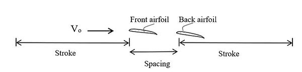
A typical arrangement for the two airfoils in a front-back direction when working as fixed wings to form a combined wing during the cruise
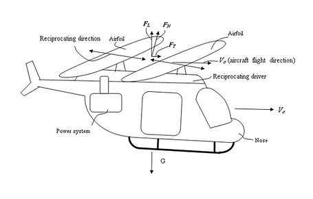
Some Typical RA-Module Driven Aircraft

Schematic Illustration of an RA-Driven Aircraft during Takeoff
During takeoff, landing, or hovering, the two RAs reciprocate on a plane substantially perpendicular to the gravitational force.
Schematic Illustration of an RA-Driven Aircraft during forwarding Flight
During forward flight, the reciprocating plane may tilt forward to provide thrust in that direction. Similar to the forward flight, the aircraft may fly backward, right sideward, or left sideward, by tilting at least an airfoil assembly in the respective direction for cyclic control (not shown).

Schematic Illustration of an RA-Driven Aircraft Employing a Propeller for Thrust
Like a fixed-wing airplane, a propeller may be employed to provide thrust while an RA module provides lift. The reciprocating driver and propeller may share the same power source (not shown). During takeoff, most of the power is used to drive the reciprocating airfoil module. Once the aircraft is in the air and gaining flight speed, the power gradually shifts to the propeller, as less power is needed by the airfoil module to generate the same lift during the cruise (see Technical Data). At a sufficiently high flight speed, the reciprocating motion of the airfoils may be optional and the airfoil module may stop reciprocating and function as fixed wings.

Schematic Illustration of an RA-Driven Aircraft Powered by a Jet Engine
A jet engine may be employed to power RA VTOL aircraft. During takeoff, most of the jet-engine power is used to drive the reciprocating wing module through an auxiliary turbine or transmission that extracts power from the jet engine. Once the aircraft is in the air and gaining flight speed, the energy gradually shifts to the jet for thrust, as less power is needed by the wing module to generate the same lift at a higher speed (see Technical Data). When the flight speed is sufficiently high, the wings’ reciprocating motion stops, and the wings are locked in place by a locking mechanism (not shown). The wings thus would function as fixed wings, and the aircraft operates as a conventional jet. More than one jet engine may be installed that may share the auxiliary power or transmission system. The removal of the rear wings in the above figure is also an option.
Advantages of RA-driven Aircraft
Compared to helicopters or rotorcraft, the RA VTOL aircraft according to this invention may have the following technological advantages:
1. Significantly improved safety and reliability.
The motion of the airfoil of this invention is linear and reciprocating, and the primary concern related to potential vibration is the balance of the inertia forces and moments due to the reciprocating motion. The system may be easily balanced by using more than one airfoil unit similar to the use of multiple horizontally-opposed pistons/cylinders in a reciprocating compressor. Unlike the situation in helicopters, even if the balance is imperfect, it is unlikely to cause catastrophic failure due to the nature of bidirectional motion. As a result, many difficult issues related to helicopters, such as anti-torque mechanisms and in-flight control of vibration and instabilities, are removed. Thus, an aircraft built upon the system of this invention may have significantly improved safety and reliability.
2. Much reduced costs.
The present system may employ airfoils similar to conventional fixed-wing airfoils and a conventional crankshaft driver similar to that in a reciprocating compressor with costs potentially much lower than that of the main rotor system in a helicopter. The lower costs of the aircraft of this invention may enable their penetration into mass markets.
3. Great modularity and controllability.
Multiple airfoil assemblies may be flexibly deployed at different locations of a vehicle for the benefits of the operation and balancing inertia forces and moments. For example, a plurality of airfoils may be arranged on the top or bottom surface of a vehicle, which may share the same reciprocating driver or be driven by separate drivers. Additionally, more than one airfoil assembly may be deployed in a vertical direction, which may share the same reciprocating driver. For helicopters, however, the deployment of multiple rotors is a challenging undertaking. For these reasons, an aircraft of this invention may be able to deploy much larger airfoil area per unit volume of the aircraft main body, resulting in significantly reduced footprint as compared to a helicopter of similar loads, which may enable entering passenger transportation markets in crowded urban areas.
4. Greatly improved energy efficiency, flight range, and flight speed compared to helicopters.
The performance of a reciprocating airfoil may match or exceed the performance of a fixed-wing of similar size and can have a lift and lift-to-drag ratio much greater than those of a helicopter main rotor. Consequently, an aircraft equipped with the present lift or thrust system could have a significantly improved flight range due to the greatly increased energy efficiency. The aircraft of this invention can also fly much faster than the helicopter because the reciprocating airfoils of this invention may be shaped like fixed wings and function as fixed wings during the cruise. The aircraft of this invention is thus a natural extension of fixed-wing aircraft with added functionality for vertical takeoff and landing.
5. Significantly reduced performance difference between the infinite-span airfoil and finite-span wing.
In a fixed-wing aircraft, the lift-to-drag ratio of a finite-span wing is significantly lower than that of a corresponding infinite-span airfoil due to the trailing-edge vortex that induces a downward velocity component, called downwash. Due to the reciprocating motion of the airfoil of this invention, at a sufficiently high frequency, the induced downwash may be difficult to be established. Considering the motion of an airfoil with a finite span moving from the right end to the left end in a stroke, the downwash may attempt to develop near the trailing edge at the right end of the airfoil. However, before the downwash may have fully established, the airfoil may have reached the left dead end. The left leading edge moves downward to become a trailing edge and the right trailing edge moves upward to become a leading-edge while the airfoil changes direction and moves from the left to the right. These combined actions may quickly eliminate the downwash before it is fully established. Consequently, the lift-to-drag ratio of the airfoil of this invention with a finite span may potentially approach that of a reciprocating airfoil with an infinite span.
6. Inherited ability to adjust the angle of attack (AoA) or tilt airfoils in desired directions when working as fixed wings would enhance the ability of the aircraft to maintain stability when encountering turbulence during the cruise.
*Yiding Cao, Reciprocating Lift and Thrust Systems, US patent pending, Priority date: March 12, 2018.
Yiding Cao, Reciprocating Lift and Thrust Systems, International Patent Application: PCT/US2019/021636.
Technical Data
Computational Data of a Reciprocating Airfoil (S1223) using Fluent
Computational Method:
The governing equations including continuity and momentum have been solved using Ansys Fluent 16 commercial code. The coupled algorithm along with PRESTO scheme was used to solve the Navier-Stokes equations. The realizable k-ε model with enhancing wall function is used as the turbulence model in this study. The second-order upwind and first-order method were used for space and time discretization respectively. The Dynamic Mesh Motion available in Ansys Fluent was used to model the airfoil motion as a moving rigid body. The airfoil velocity U (t) and rotational velocity around the airfoil’s point of impact Ω (t) was implemented by User-Defined functions (UDF) using the dynamic mesh macro DEFINE_CG_MOTION. The time step for all simulation was set to 2e-5 s.


Plot 1: Two-dimensional Computational Results using a Standard Airfoil (S1223).
The plot shows averaged lift coefficient, drag coefficient, and lift to drag ratio as a function of the angle of attack (AoA) for both forward and reverse strokes, with a chord of 0.25 m, airfoil planform area 0.25 m2, and a stroke S of 2 m. Both the lift and drag coefficients are calculated based on an average airfoil reciprocating speed (V) of 50 m/s with zero aircraft cruise speed. A positive AoA for both strokes is maintained through rotating the airfoil around the leading edge near each end of the stroke. An animation related to the reciprocating motion of the airfoil and the velocity contours is presented below:
Animation of Numerical Results for the Motion of an RA (S1223) and associated Flow Fields

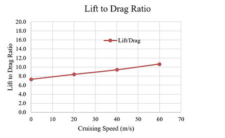
Plot 2: Three-dimensional Computational Results of a Finite-span Reciprocating Airfoil (S1223) at different Aircraft Flight Speeds
The plot shows lift and drag (left), and lift-to-drag ratio (right) as a function of aircraft flight speed at an angle of attack of 12 for both forward and reverse strokes, with a chord of 0.25 m, aspect ratio: 16, a total airfoil planform area: 1 m2, an average airfoil reciprocating speed of 50 m/s, and a reciprocating stroke of 2 m. A positive AoA for both strokes is maintained through the rotation of the airfoil around the leading edge near each end of the stroke.

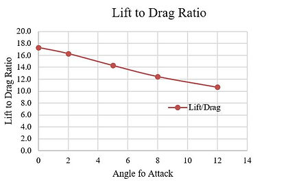
Plot 3: Three-dimensional Computational Results of a Finite-Span Reciprocating Airfoil (S1223) as a Function of Angles of Attack at a Cruise Speed of 60 m/s
The plot shows lift and drag (left), and lift-to-drag ratio (right) as a function of angle of attack for both forward and reverse strokes at an aircraft cruise speed of 60 m/s (134 mph), with a chord of 0.25 m, aspect ratio: 16, a total airfoil planform area: 1 m2 , an average airfoil reciprocating speed of 50 m/s, and a reciprocating stroke of 2 m. A positive AoA for both strokes is maintained through the rotation of the airfoil around the leading edge at each end of the stroke.
Discussions of the computational data:
1. The results in Plot 2 show that as the aircraft’s speed is increased, the lift is increased greatly accompanied by a significant improvement in the lift-to-drag ratio. During the cruise, the actual airflow across the reciprocating airfoil is the superposition of the reciprocating motion of the airfoil and the airflow due to the motion of the aircraft, which improves the airfoil performance. At an aircraft speed of 50 m/s (about 112 mph), the wing loading of the reciprocating airfoil is above 7,000 N/m2 or above 700 kg/m2 with a lift-to-drag ratio about 10, which is compared to a wing loading range of 500 - 700 kg/m2 for most fixed wings of airliners. The results herein greatly exceed the performance of the main rotors of helicopters and match or exceed the performance of most fixed wings. When the aircraft speed increases to 60 m/s, the wing loading would approach 900 kg/m2 with a lift-to-drag ratio above 10. With a further increase in aircraft speed, the airfoil loading would continue to rise, which may exceed the loading needed. In this case, the airfoil may work at a much lower AoA or a much reduced reciprocating speed, both of which can significantly reduce the power consumption of the aircraft. Eventually, at a given speed, the airfoil could stop reciprocating and work as a fixed-wing with a suitable AoA.
2. Plot 2 also indicates that the lift at takeoff or landing, corresponding to zero cruise speed, is about 3,098 N/m2 or 316 kg/m2. This wing loading is lower than the range of 500-700 kg/m2 of airliners; but this comparison is not reasonable. It is well known that during airliners' takeoff and landing, high-lift devices are employed to produce enough wing loading accompanied by drastically reduced lift-to-drag ratio or significantly increased power consumption. In the present computations, however, the airfoil used is a clean one without high-lift devices, with a decent lift-to-drag ratio. Still, the reciprocating airfoil could work at a higher AoA or reciprocating speed to match the wing loading of airliners at the takeoff. Furthermore, as will be discussed on the web page of Design Considerations, reciprocating airfoils incorporating high-lift devices may be employed for takeoff or landing to double or triple the wing loading. Because of the ability to adjust the AoA of the present system, the AoA of the airfoil with high-lift devices could be significantly reduced during the cruise for a higher lift-to-drag ratio to reduce power consumption.
3. Compared to the 2D results in Plot 1 at the same angle of attack, the 3D result in Plot 2 shows only 27% reduction in the lift-to-drag ratio, which is significantly lowered reduction than that for a fixed-wing. Because of the reciprocating motion of the finite-span airfoil, the trailing-edge vortex effect related to a fixed-wing is diminished and the performance difference between an infinite-span reciprocating airfoil and a corresponding finite-span wing is significantly reduced. The 3D performance reduction compared to the 2D performance may be due to airfoil tip vortex (similar effect to the main rotor of a helicopter), which may be reduced by using various winglet techniques.
4. Plot 3 shows the performance of the same airfoil at a cruise speed of 60 m/s as a function of the angle of attack. At zero angle of attack, the lift-to-drag ratio is increased to above 17 exceeding the performance of most fixed wings, while maintaining a good airfoil loading. The airfoil S1223 as a fixed airfoil generates positive lift until an AoA below -5 degree; a further reduction in the angle of attack may further increase the lift/drag ratio. However, working at a zero angle of attack means no need to rotate the airfoil at each end of a reciprocating stroke during the cruise, thus the functionality of changing the angle of attack at each end of the stroke may be deactivated in relatively high-speed flights to increase the reliability of the reciprocating system. Also, according to the animation results, except for the downwash, the disturbed air region may be substantially limited to the length of the reciprocating stroke. Therefore, reciprocating airfoils may be more densely packed.
5. The reciprocating airfoils of this invention may match or outperform fixed wings of similar scale and greatly outperform rotors of helicopters. The result here is based on a standard fixed-wing airfoil S1223. With specially designed airfoils for reciprocating motion, the performance could be further improved.
Design Considerations
1. Consider a sample design using the data from Plot 2 on the web page of Technical Data. At zero cruise speed that corresponds to takeoff or landing of the aircraft, the reciprocating wing loading is 3,098 N/m2, the ratio of the lift to drag is 7.3, and the average reciprocating speed is 50 m/s. As shown on the web page of Innovation, an RA module of two airfoils is preferably used. If each airfoil would have a stroke of 3 m, an average chord of 0.375 m, and a span of 8 m, the total wing area of the module would be 6 m2. The total lift or maximum takeoff weight would be 18,588 N or 1894.8 kg (1.89 ton). By using the lift-to-drag ratio of 7.3 and the average reciprocating speed of 50 m/s, the maximum power consumption would be 127.3 kW or 171 hp, which is translated to 67.4 kW/ton-weight. For most commercial helicopters, the power-to-maximum weight ratio is between 200 kW/ton to 300 kW/ton. Therefore, the maximum power requirement of the RA driven VTOL aircraft would be less than one-third of that required by helicopters. Furthermore, the power requirement per ton herein is much lower than that of some small planes without VTOL capabilities.
2. It is known that for commercial duties of helicopters or small planes, the overall energy efficiency is determined mainly during the cruise because the takeoff and landing times are normally much shorter than the entire flight duration. As shown in Plot 3 on the web page of Technical Data, at a cruise speed of 60 m/s (134 mph), the wing loading could approach 5,000 N/m2 when the AoA approaches zero, well above the takeoff loading of about 3,000 N/m2. More importantly, the flight would enjoy an outstanding lift-to-drag ratio of nearly 18. By using the same lift coefficient, the reciprocating speed could be reduced from 50 m/s to about 40.8 m/s to match the weight of the aircraft, and the power consumption of the aircraft would be only about 23.1 kW/ton at a zero AoA of the airfoil S1223. At sufficiently high cruise speed, the airfoils could stop reciprocating and function as fixed wings. In the present case, at a cruise speed above 65 m/s (145 mph), the fixed wings could provide enough lift for the operation of the aircraft by using the data of S1223 as a fixed-wing. At a further increased cruise speed, the S1223 airfoil could be adjusted to a negative AoA to reduce the drag and the power consumption of the aircraft.
3. As discussed in the Technical Data related to Plot 2, the reciprocating wing loading at takeoff or landing, corresponding to zero cruise speed, is lower than the range of airliners. However, the lift at the takeoff or landing can be increased by increasing the reciprocating speed of the airfoil or by operating the airfoil at a higher AoA. It was also mentioned that the airliners' high lift capacity during takeoff is achieved by employing high-lift devices while in the present case, clean one without high-lift devices is used. For heavy lifting duty of the present aircraft, high-lift devices may also be incorporated into the reciprocating airfoil. As an example, the figure below shows schematically a reciprocating airfoil incorporating a leading-edge slat and a trailing-edge flap. When a retractable mechanism is difficult to be deployed, perforated holes are used that provide flow passages while retaining the integrity of the airfoil. With the use of the high-lift devices, the lift capacity during the takeoff or landing could be doubled or tripled. Once the aircraft is in the air and reaches certain flight speed, the AoA of the airfoil with high-lift devices may be reduced significantly or work in a negative AoA to maintain a smaller drag while proving adequate lift.
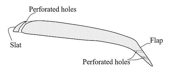
Schematic drawing of a reciprocating airfoil with leading-edge slat and trailing edge flap
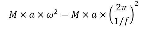
4. In general, the performance characteristics of a reciprocating airfoil system may depend on the ratio of the stroke to chord, and the system may be scalable. The sample calculation above is based on an aircraft having a maximum takeoff weight of about 2 ton. With the use of high-lift devices, the takeoff weight may be increased to 6 ton. Now, consider a case to increase the stroke to 30 m with the same wing loading during the takeoff, the potential maximum takeoff weight could be increased to 60 ton. The relation between the average reciprocating speed V, the stroke S, and the reciprocating frequency f (reciprocating cycles per second) is:
This means that for the same average reciprocating speed V, an increase to 10 times original stroke S could reduce the frequency f to one-tenth of the original value. The outcome is very beneficial to structural considerations because the crankshaft that drives the airfoils could run at a very slow speed. For example, to achieve an average speed of 50 m/s, if the stroke is 2 m, the frequency would be 12.5 Hz. If the stroke is increased to 20 m, for the same velocity, the frequency would be reduced to 1.25 Hz, corresponding to a crankshaft speed of 75 rpm. Similarly, instead of scaling up, the reciprocating system could also be scaled down for applications with a takeoff weight of less than 50 kg.

5. When a crankshaft is employed to drive an airfoil, inertia force related to the acceleration and deceleration of the reciprocating motion would be a limiting factor to be considered. In general, the inertia force would be scaled to:
wherein M is the effective mass of the reciprocating system and a is the radius of the crank, which is normally one half of the stroke, S/2. Consequently, a desired increase in stroke would need to increase a, resulting in increased inertia force. Stroke-enhancement mechanisms that could double or triple the stroke for a given crank radius could be employed. For example, without the use of a stroke enhancement mechanism, for a stroke of 2 m, the crank radius would be 1 m. However, with the stroke-enhancement mechanism, the crank radius could be reduced to 0.33 m. Several stroke-enhancement mechanisms have been described by the PCT application cited on the web page of Innovation.
6. An important component of the reciprocating airfoil system is the track that guides and supports the airfoil assembly. The track is preferably linear and having the ability to guide the designed reciprocating motion with minimum friction while restraining the motion of the airfoil assembly in other directions. Although aircraft backbone structures may be used as the tracks, track cross-sections of two design examples are schematically shown below:
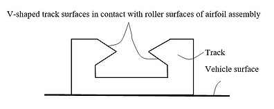

Schematic drawings of two tracks with V-shaped contact surfaces
Yet another important component shown on the web page of Innovation is the pitch control mechanism. The pitch control mechanism could be an electromagnetic, an electrical, or a hydraulic control mechanism, but a practical one may be a mechanical control mechanism based on a rack-pinion gear unit in conjunction two stoppers disposed, respectively, near the left and right dead ends of a reciprocating stroke. While both stoppers do not reciprocate with the airfoil assembly, the rack-pinion gear is part of the airfoil assembly and reciprocates with the airfoil assembly. During the operation, for example, before the airfoil assembly reaches the left dead-end, the left end of the rack gear would trike the left stopper, which triggers a rightward motion of the rack gear and then the action of the pinion gear and the associated push/pull tubes to rotate the airfoil by an angle while the airfoil changes direction and moves from the left to the right. Similarly, before the airfoil assembly reaches the right dead end, the right end of the rack gear would strike the right stopper to rotate the airfoil by an angle while the airfoil changes direction and moves from the right to the left. One of the inherited advantages is that near each end of a stroke, the airfoil velocity and the airfoil loading are almost zero during takeoff or landing so that the power consumption of the control mechanism would be very limited. More detailed descriptions on the control mechanism have been provided by the patent application cited on the web page of Innovation, along with other aspects of RA driven VTOL aircraft.
7. As introduced, a reciprocating cycle may consist of two strokes. The stroke that produces the highest lift between the two strokes may be labeled as primary or forward stroke while the other stroke may be labeled as reverse stroke. Each stroke would correspond to an airfoil path and the two strokes would involve two paths. It is hypothesized that the interaction of these two paths and their created flow conditions would be a significant factor to determine the performance of a reciprocating airfoil. These two paths could be overlapped, partially overlapped, or separated. It is further hypothesized that a higher degree of separation of these two paths could produce a better performance in terms of lift or lift-to-drag ratio. The rotation of the airfoil by an angle around the leading edge near each end of the stroke, as shown in the Technical Data, is an example to attain a higher degree of path separation. If a rowing process is considered to be cyclic, each cycle having a drive path and a recovery path, the drive path is in the water while the recovery path is the air, completely separated from the drive path with almost no interaction between these two paths. In the present aerodynamic applications, however, the interactions between the flow fields created by the two paths may be difficult to be avoided even if the two paths are separated. Mechanisms that could attain a higher degree of separation of the two paths have been described by the PCT application cited on the web page of Innovation.
Potential Industrial Products
A first product category from the present invention is aircraft within a broad category of vertical takeoff and landing (VTOL) aircraft that could facilitate the functionalities of fixed-wing aircraft, helicopters, and other powered aircraft. In addition to the aircraft for conventional transportation purposes, the reciprocating lift and thrust systems may be used for military jets, unmanned aerial vehicles (UAV), recreational aircraft, and personal vehicles. When the system of this invention works as a thrust means, it may replace the propeller or jet engine of fixed-wing aircraft and use a runway for takeoff and landing. It is believed that the products introduced through this invention could potentially transform the entire VTOL aircraft industry.
A second product category is flying motor vehicles, including flying cars, flying buses, flying trucks, flying motorcycles, and flying off-road vehicles, which can be produced by modifying the RA driven VTOL aircraft.
Yet the present invention could be adapted for many other industrial applications such as watercraft or waterborne-vessel propulsion to generate thrust and move a ship, a submarine, or a boat across water.
GET IN TOUCH
If you have any questions regarding this new aircraft or would like to have potential collaboration with us, please contact Dr. Yiding (Eddie) Cao through the following email: